The Open-Motion System
The Open-Motion hardware platform consists of three primary components.
| Component | Description |
|---|---|
| Console | Houses the laser, electronics and optics, power cable, and an on/off switch on the back. Should never be opened — risk of laser radiation exposure and electrical hazards. |
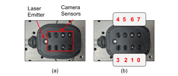
| Sensor Module(s) | Wearable modules containing an array of camera sensors (configurable via software) and on-module histogram processing. |
| Laser | Class 1, 795 nm, pulsed, integrated inside the Console. |
Do not disassemble the Console
The Console contains a Class 3 laser source and high-voltage electronics. Opening the enclosure risks permanent eye injury and electric shock and voids all warranties.
Open-Motion specifications
Console
| Operating voltage | 100–240 VAC, 50–60 Hz, 0.5 A |
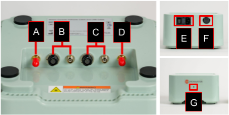
| Connections | 1× USB-C (USB 3.0) 1× SMA trigger (input) 1× SMA sync (output) 2× electrical ports (left / right) 2× optical ports (left / right) |
| Device status | LED indicator |
| Dimensions (W × H × D) | 9.8 × 3.0 × 6.3 in (250 × 75 × 160 mm) |
| Weight | 3 lb (1.36 kg) |
Sensor Module
Each Open-Motion device uses two Sensor Modules.
| Image sensors | 1/3.52" CMOS |
| Resolution | 1920 × 1280 |
| Frame rate | 40 Hz |
| Pixel size | 2.2 μm × 2.2 μm |
| Dimensions (W × H × D) | 2.1 × 1.6 × 2.5 in (52.5 × 39.4 × 64.1 mm) |
| Cable length | 6 ft (2 m) |
| Weight | 0.5 lb (0.2 kg) |
Laser
| Laser classification | Class 1 |
| Wavelength | 795 nm |
| Pulse duration | 250–1000 μs |
| Pulse repetition rate | 40 Hz |
| Average power | 12 mW |
| Energy per pulse (at delivery fiber tip) | 300–500 μJ |
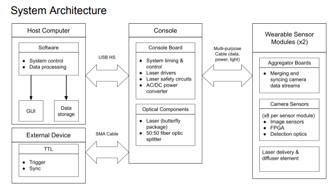
System architecture
The general system architecture connects the host PC to the Console over USB, and the Console to one or two Sensor Modules over paired electrical and optical links.
USB cable requirement
The USB cable must be a USB-A to USB-C cable and can only be sourced from
Openwater (part number 100-00049). Substituting a generic cable can
cause data integrity issues at full link speed.
System signals
Console signal pathways
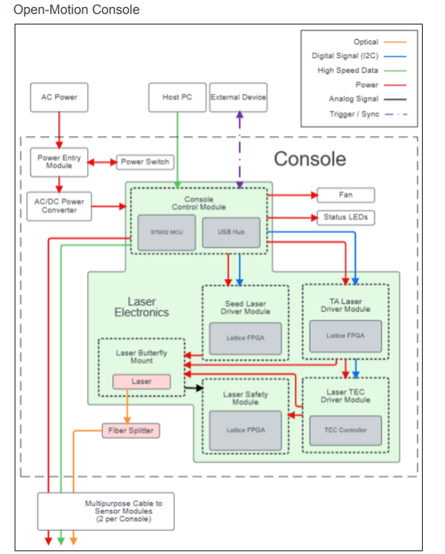
The Console signal pathways cover:
- USB host communication
- Sensor Module electrical and optical interfaces
- Laser control and safety interlocks
- SMA trigger input/output paths
- Status LED control
Sensor Module signal pathways
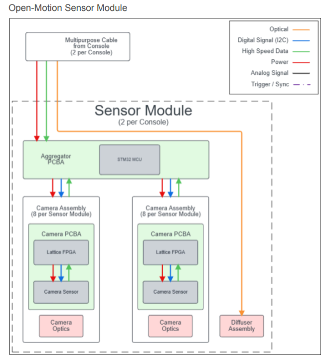
The Sensor Module signal pathways cover:
- Camera SPI inputs (8 cameras per module)
- Aggregation logic
- USB high-speed output to the Console
- Internal clocking and frame sync
Next: Software Development for tech stack, architecture, and the firmware/host/test layers.