The Open-LIFU System
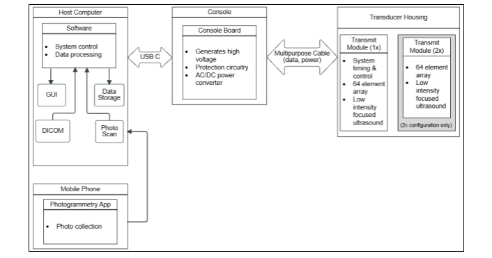
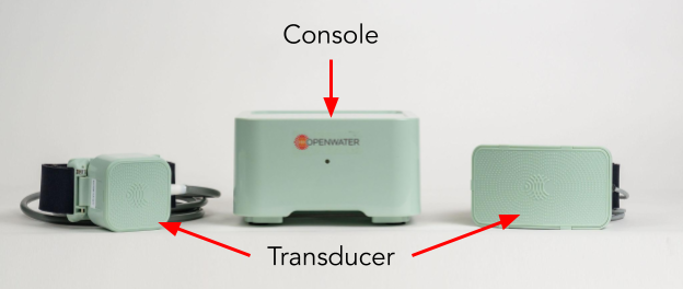
The Open-LIFU hardware platform consists of three primary components.
| Component | Description |
|---|---|
| Console | Main control unit containing high-voltage power supplies, timing controllers, and communication interfaces. Generates and coordinates the electrical signals that drive the ultrasound transducer. |
| Transducer | Wearable headset-style housing containing one or more Transmit Modules (each a 64-element 2D matrix array), a deformable acoustic coupling pad, and unique geometric features for spatial tracking. |
| Supporting hardware | Android mobile device (photogrammetric reconstruction), USB-C cable to PC, optional water-tank testing accessories. |
Investigational device — do not modify without recharacterization
All Open-LIFU transducers and transmit modules are factory calibrated. Reconfiguring or modifying any transducer immediately voids the factory calibration, requiring users to recharacterize the transducer to ensure it complies with all necessary application-specific requirements.
The transducer is not watertight. Never submerge it in water. Doing so may lead to electric shock or damage.
Open-LIFU device specifications
Console
| Operating voltage1 | 100–240 VAC, 50–60 Hz, 1.2 A (120 W) — or 3.5 A (180 W) |
| High-voltage output1 | ±10–60 V (120 W) — or ±10–65 V (180 W) |
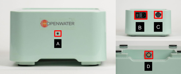
| Connections | 1× USB-C (USB 3.0) 1× 12-pin socket (transducer) |
| Device status | LED indicator |
| Dimensions (W × H × D) | 9.8 × 3.0 × 6.3 in (250 × 75 × 160 mm) |
| Weight | 3 lb (1.36 kg) |
Console status LED:
| Color | Pattern | Meaning |
|---|---|---|
| None | Off | System is off |
| Green | Solid | System is on and ready |
| Blue | Solid | System is on and sonicating |
| Blue | Pulsing | Error |
Transmit Module
Each transmit module is a self-contained beamforming unit. The transducer housing contains one (1×) or two (2×) modules connected via ribbon cable.
| Operating voltage | 12 VDC, 1.2 A |
| High-voltage input | ±0–100 V |
| Beamformer clock | 10 MHz |
| Array center frequency | 155 kHz or 400 kHz |
| Number of elements | 64 (per module) |
| Array dimensions | 40 × 40 mm |
| Element size (W × L) | 4.7 × 4.7 mm |
| Element pitch | 5 mm |
| Overall dimensions (W × L × D) | 2.0 × 2.6 × 1.2 in (52 × 67 × 30 mm) |
| Connections | 1× 12-pin socket (input) 1× 30-pin socket (input) 1× 30-pin socket (output) |
| Device status | LED indicator |
| Weight | 0.4 lb (187 g) at 155 kHz · 0.3 lb (132 g) at 400 kHz |
Transducer configurations
Open-LIFU transducers ship as wearable headsets with a soft strap, a disposable coupling pad, and padding to prevent slipping. The outer faceplate has an embossed pattern used for spatial localization. The faceplate can be removed to access the transmit modules for service but should not be removed during normal use.
Two standard configurations are offered:
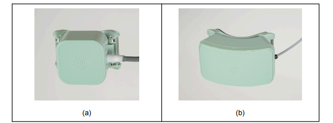
- 1× (single transmit module) — for shallower targets
- 2× (dual transmit module) — for deeper targets
Both are available at 155 kHz or 400 kHz. Custom configurations (more modules, alternative arrangements) are supported within the architecture but are beyond the scope of this document and require recharacterization.
Transmit module acoustic output
Representative values — exact values vary per serialized transducer.
| 1× 155 kHz | 1× 400 kHz | 2× 400 kHz | |
|---|---|---|---|
| Peak P- @ 60 V and (0, 0, 50) mm | 0.7 MPa | 1.1 MPa | 2.16 MPa |
| Derated P- (Pr.3) @ 60 V | 0.68 MPa | 1.02 MPa | 2.01 MPa |
| Voltage | ±10–60 Vmax | ±10–60 Vmax | ±10–60 Vmax |
| Mechanical Index (MI) in water2 @ 60 V and (0, 0, 50) mm | 1.7 | 1.8 | 3.18 |
| Axial FWHM @ (0, 0, 50) mm | 34 mm | 31 mm | 15 mm |
| Transverse FWHM @ (0, 0, 50) mm | 8 mm | 4.5 mm | 4.7 mm (elev.) / 2.4 mm (azim.) |
| Axial steering range | 4–6 cm | 4–7 cm | 3–11 cm |
| Transverse steering range | ±1 cm | ±1.5 cm | ±2 cm |
| Pressure–voltage sensitivity @ (0, 0, 50) mm focus | 6 kPa/Vpp @ 30 mm | 9.9 kPa/Vpp @ 45 mm | 18 kPa/Vpp @ 50 mm |
Sonication sequence specifications
Programmable sonication parameters and their typical / minimum / maximum values:
| Category | Parameter | Description | Typical | Min | Max |
|---|---|---|---|---|---|
| Pulse | Frequency (kHz) | Pulse center frequency | 155 or 400 | — | — |
| Pulse | Focal Pressure (kPa) | Peak negative pressure at target | 500 | 0 | 1200 |
| Pulse | Duration (ms) | Pulse duration | 5 | 0.01 | 100 |
| Sequence | PRI (ms) | Pulse repetition interval | 100 | 10 | 1000 |
| Sequence | Pulse count | Number of pulses per train | 300 | 1 | 1000 |
| Sequence | PTRI (s) | Pulse train repetition interval | 30 | 0 | 120 |
| Sequence | Train count | Number of pulse trains | 20 | 1 | Protocol-dependent |
System architecture
A mobile device is used to help localize the transducer by capturing a series of images, which are then reconstructed into a 3D mesh using local computer processing or cloud compute. The PC runs the Open-LIFU Desktop Application (or the Slicer extension) to plan, configure, and run sonications. The application communicates with the console to configure the high-voltage supply and transducer to execute a Solution. The transducer is placed on the subject using coupling gel and a disposable coupling pad.
System hardware
Console
The console connects to a PC via a USB-C cable and generates the positive and negative supply voltages used to drive the transducer.
Transducer
The transducer uses a factory-configurable headset-style housing containing one or two transmit modules — 1× or 2× configuration, at either 155 kHz or 400 kHz.
Transducer orientation
The transducer has an up–down orientation. Mechanical features prevent upside-down assembly, and a debossed arrow on the side of the body indicates the "up" direction. The cable exits toward the subject's left ear when the transducer is worn on the forehead.
A soft padded foam frame on the transducer provides a comfortable, non-slip interface for placement on a subject. The transducer also has a removable curved "veneer" attached to it, used for transducer localization. Do not remove or damage the veneer.
Coupling Pad
The coupling pad sits inside the transducer to ensure good acoustic coupling between the transducer and the subject.
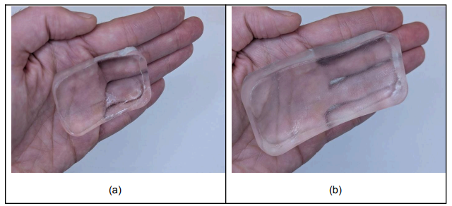
Coupling pads are non-sterile and composed of a water-based polymer hydrogel shaped to fit the faceted transducer faces and conform to curved surfaces (e.g., the forehead). The coupling pad is needed to:
- Eliminate air interfaces between ultrasound probes and skin
- Reduce acoustic impedance mismatch
- Improve transmission of ultrasound energy
| Density | 1.12 (10³ kg/m³) |
| Speed of sound at 35 °C | 1520–1620 m/s |
| Hardness | 00 < 40 |
| Peeling strength | 220 g |
Coupling pad packaging
When using coupling pads, open packaging carefully at marked areas to avoid tearing or damaging the pad.
Additional hardware requirements
PC
A PC is required to download and run the Open-LIFU application. Recommended specifications:
- Graphics card: NVIDIA CUDA 11+
- Operating system: Windows 11+
- Network: recommended (optional for installation, optional for cloud services)
- Storage: at least 5 GB of free disk space
Android phone
A mobile device is required for transducer localization through photogrammetric reconstruction. Official support is provided for Google Pixel phones — tested on the Pixel 5, 7, 9, and 10. Other phones meeting the minimum specifications (e.g., Samsung Galaxy A16, Motorola moto g) should also work, but full compatibility cannot be guaranteed. For help with non-supported phones, visit the Discord.
Minimum phone specifications:
- Android 14 or newer
- Dual camera: 12.2 MP, f/1.7, 27 mm wide, 1/2.55", 1.4 µm, dual-pixel PDAF, OIS · 16 MP, f/2.2, 117° ultrawide, 1.0 µm
- Accelerometer, gyroscope
Next: Software Development for the five-layer software stack, the SDK, and transmit-module wiring diagrams.