Open-LIFU Software Development
Overview
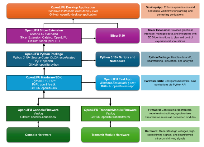
The Open-LIFU software stack comprises five coordinated layers:
- Embedded firmware running on the console and transmit modules
- Hardware interface SDK — a lightweight Python library for direct device control
- Open-LIFU Python toolbox — core sonication planning algorithms
- Slicer extension — graphical UI modules built on 3D Slicer
- Desktop application — top-level executable that bundles all of the above into a guided clinical workflow
Each layer is modular and open-source, allowing for extensibility and integration. The middle three layers can each be accessed directly through compatible programs for testing and development.
Licensing
All Open-LIFU software is licensed under the AGPL v3. Hardware designs are released under Creative Commons ShareAlike 4.0. See Best Practices → License for the full obligations.
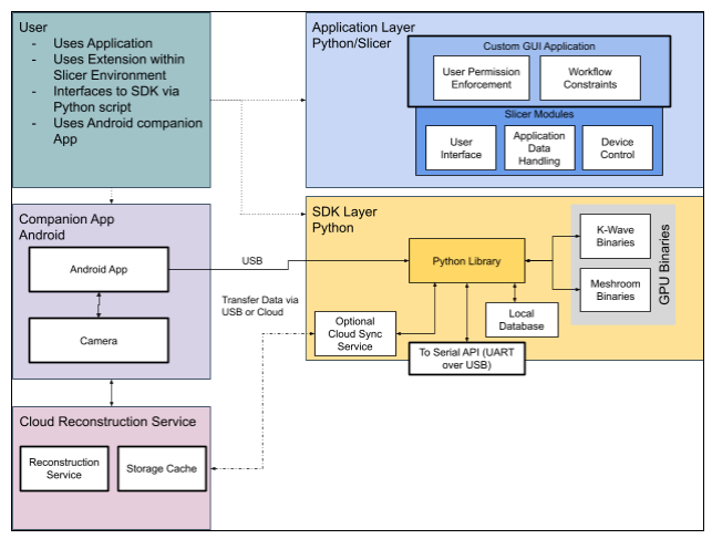
Software architecture
A complementary view, showing the application layer alongside the SDK layer, companion app, and cloud reconstruction service:
Open-LIFU Desktop Application
The Open-LIFU Desktop Application is an executable that provides a guided workflow for planning and executing sonications. It assigns user-specific permissions and workflows and is the best way to prevent accidental system misconfiguration. The desktop application is a custom build of the open-source 3D Slicer with the Open-LIFU extension installed.
| Repository | openlifu-desktop-application |
| Form factor | Custom 3D Slicer build with bundled OpenLIFU extension |
| Best for | Day-to-day planning and execution of sonications |
Open-LIFU Slicer Extension
The graphical UI elements used by the Desktop Application live in the
Open-LIFU Slicer Extension. Advanced users and developers can access
these underlying modules directly from a vanilla 3D Slicer install via the
Extension Manager (search "OpenLIFU"), or by cloning the
SlicerOpenLIFU
repository. This allows experimental modification of different steps in the
sonication planning process and incorporation of external Slicer module
functionality.
Reduced guardrails outside the Desktop App
Many of the safety guardrails present in the Desktop application are not active when the Slicer modules are used directly. See Slicer Modules for the advanced workflow and its caveats.
Open-LIFU Python
The core data classes and methods are written in Python and live in the
openlifu-python
repository. Some computationally intensive methods call GPU-accelerated
binaries. These classes can be used directly by experienced developers to
plan and control sonications and are fully customizable. Many classes are
provided as abstract base classes with one or more example-implemented
subclasses, serving as templates for adding customized classes with more
advanced and experimental features.
| Repository | openlifu-python |
| Framework | Python |
| Function | Orchestrates data management, beamforming computations, acoustic simulation, and field analysis |
| Platform support | Windows 11+, Linux |
| Extensibility | Open-source and modular (Python 3.10–3.12) Integrates with NumPy, Pandas, Jupyter, and other scientific tools API documentation in openlifu-python/docs |
For a guided introduction, see the Open-LIFU Quick Start or the tutorials repository.
| Repository | Description |
|---|---|
| Tutorials | Interactive guides that demonstrate the functionality and usage of the openlifu library. Covers the basics of initializing the library and creating fundamental objects, demonstrating how the library connects to and queries databases, and generating analytical solutions and evaluating results. |
| Test App | Python-based GUI for the validation and testing of Open-LIFU hardware. |
Hardware interface SDK
While the Python package provides comprehensive planning tools, the hardware interface has been split into its own repository so that applications requiring direct control of the hardware — without the sonication planning machinery — can be built using only a lightweight interface layer. This layer runs on the PC and provides device control and data acquisition.
| Repository | openlifu-sdk |
| Framework | Python |
| Function | Data management Sonication pre-planning ("virtual fitting") Photogrammetric reconstruction using Meshroom Beamforming computation and acoustic simulation using k-Wave Beam field analysis Hardware configuration and control |
| Platform support | Windows 11+, Linux |
| Extensibility | Open-source and modular (Python 3.10–3.12) Integrates with NumPy, Pandas, Jupyter, and other scientific tools |
Python library installation (optional)
Direct access to the underlying logic is available via the openlifu-sdk
library. For a fuller walk-through with a smoke test and the sample
database, see the
OpenLIFU-python QUICKSTART.
# 1. Install Python 3.12

# 2. Clone the SDK
git clone https://github.com/OpenwaterHealth/openlifu-sdk.git
cd openlifu-sdk

# 3. Create a virtual environment
# Windows (PowerShell):
python -m venv env
.\env\Scripts\Activate.ps1
# Linux:
python3.12 -m venv env
source env/bin/activate

# 4. Install
pip install -e .
Embedded firmware layer
The Embedded Firmware Layer includes all firmware responsible for the low-level operation of the system, running on the console and transmit modules.
| Language | C |
| Toolchain | STM32Cube HAL and CMSIS, MISRA C guidelines applied where practical |
| IDE | Visual Studio Code |
| Structure | Code is organized for readability (clear naming, small functions, single responsibility), safety (defensive programming, bounds checking, explicit initialization), and testability (hardware abstraction, minimal global state). |
To work within this layer:
- Download the project from Git
- Open the project within Visual Studio Code
- Make necessary firmware modifications
- Build and flash following the per-repo instructions
Local data storage
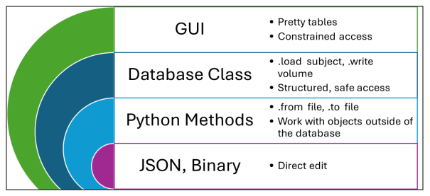
In addition to code, Open-LIFU defines structured representations of data
on disk. While the Python code and Slicer modules can handle any data that
is well-constructed into the appropriate class, a Database class provides
convenient organization of and access to protocols, subjects, and
transducers, each with nested information. System data is stored locally
in a file tree on disk in a combination of JSON for structured data and
various other file formats for binary data.
The GUI application accesses data from within such a database, while certain research applications may need to access data objects stored elsewhere via the lower-level access surfaces.
An example of the on-disk database tree (<…> represents instance IDs):
protocols/
  <pid>/
    <pid>.json
transducers/
  <tid>/
    <tid>.json
    <tid>.surf.obj
    <tid>.body.obj
subjects/
  <sid>/
    volumes/
      <vid>/
        <vid>.json
        <vid>.nii
    sessions/
      <ssid>/
        photocollections/
        photoscans/
        solutions/
        runs/
users/
  <uid>/
    <uid>.json
Cloud database
The cloud database is an active roadmap feature and is in the process of being developed.
Android companion application
Alongside the Open-LIFU PC application is a companion Android app used to capture photographs for photogrammetric reconstruction (the "Photocollections" used during transducer localization). See Open-LIFU System → Android phone for supported device specifications.
Tools used
| Category | Tools / Platforms |
|---|---|
| Version control | Git + GitHub |
| CI/CD (under development) | GitHub Actions |
| IDEs | VS Code |
| Documentation | Markdown, .docx |
| Testing | Oscilloscope, logic analyzers, unittest |
Test & validation utilities
These tools are used in development, manufacturing, and QA workflows.
| Repository | openlifu-test-app |
| Framework | Python + PyQt6 |
| Function | Set high-voltage rails and read back the values Turn on/off the transmit module(s) Perform basic command send/receive verification with the transmitter Toggle the trigger and change the target XYZ coordinates to steer the beam Upgrade firmware |
Transmit modules
Depending on the configuration, there may be one or more transmit modules inside the transducer. Each is a PCBA affixed to a PZT ultrasound transducer, encased in plastic, with a heatsink on the back.
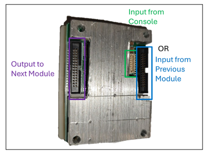
If reconfiguring the transducer, note that only the console input or the input from a previous transmit module should connect to one of the adjacent connectors; never both. Ribbon cables connect the output side of one transmit module to the input side of the next. Refer to the water-tank testing section before using a reconfigured transducer.
Recharacterization required
All Open-LIFU transducers and transmit modules are factory calibrated. Reconfiguring or modifying any transducer immediately voids the factory calibration and requires recharacterization to ensure compliance with application-specific requirements.
Transducer logical architecture
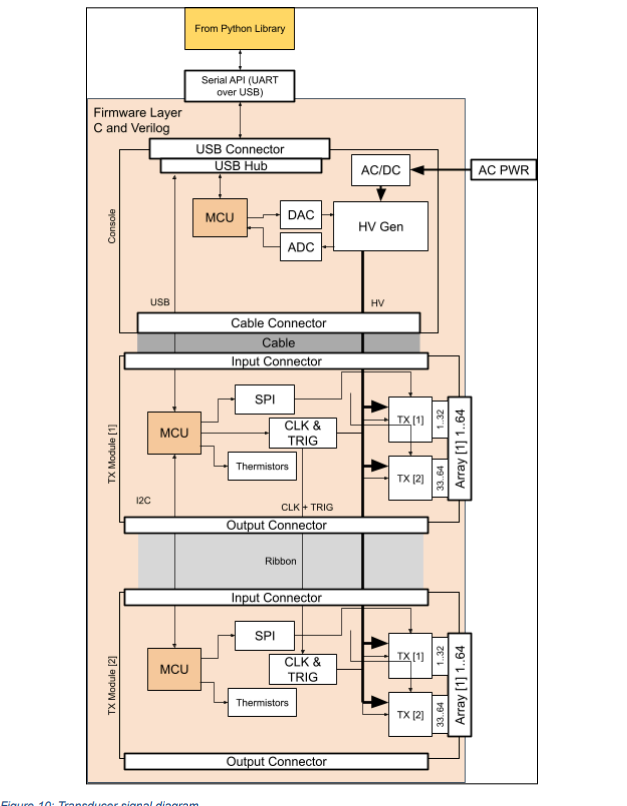
Transmit module wiring
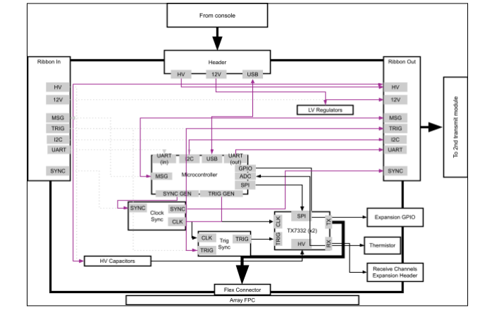
While all transmit modules contain the same hardware, the console connects only to the first module in a chain via a custom cable. That module is connected via a parallel ribbon cable to any downstream modules, over which it passes commands via I²C and generates signals broadcast to all modules for coordinating synchronized transmission. Downstream modules take input and output via ribbon cable, allowing for near-arbitrary daisy-chaining provided the HV power supply can support all connected modules.
First module in chain
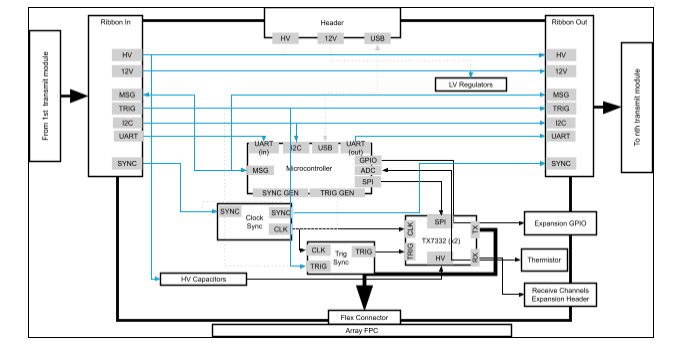
Middle module in chain
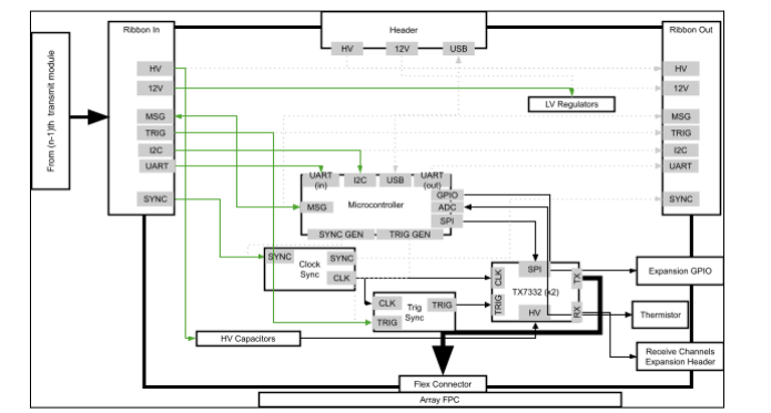
Last module in chain
Repository map
A consolidated view of the Open-LIFU software repositories:
| Layer | Repo | Purpose |
|---|---|---|
| Application | openlifu-desktop-application |
Desktop installable (custom Slicer build) |
| Slicer | SlicerOpenLIFU |
3D Slicer extension with the OpenLIFU modules |
| Python | openlifu-python |
Core sonication planning toolbox |
| SDK | openlifu-sdk |
Lightweight hardware interface library |
| Firmware | openlifu-console-fw |
Console MCU firmware |
| Firmware | openlifu-transmitter-fw |
Transmit module firmware |
| Firmware | openlifu-transmitter-bl |
Transmit module bootloader |
| Hardware (3D Scanner) | OpenLIFU-3DScanner |
Android photogrammetry app |
| Test/QA | openlifu-test-app |
Test engineering tool |